A few weeks ago we started getting an error on the dash of the 2017 Mini Cooper (which only has 43k miles on it) which said “Transmission: Secure vehicle from rolling” whenever we parked it. The car is most definitely in Park and can’t be pushed, but the computer thinks it’s not. The dealer quoted $2200 to replace the shifter assembly – ouch!
I found the new part (25-16-8-483-097)online for a bit under $600. However, I discovered on the F56 Mini forum that the common failure is actually just a broken spring inside the shifter. Since the majority of the effort is getting the interior apart to actually get access to the shifter, I figured it was worth the $10 for the replacement part off ebay and a few hours of effort to try this repair myself. I figured if I got it apart and it wasn’t the spring, then most likely it’s the solenoid inside the unit and at that point I could order the $600 part with the only downside being the car would be undriveable for a few days.
In fairness all of the info and photos below are gathered from a number of youtube links. However I find youtube to be a really poor way of following instructions when doing vehicle repairs, so I translated the mix of 3 different videos into one procedure shown below.
Tools
Aside from a regular set of philips and flat head screwdrivers, you’ll need some torx bits and a socket set or wrenches for this. Nothing fancy.
Gear Selector Removal
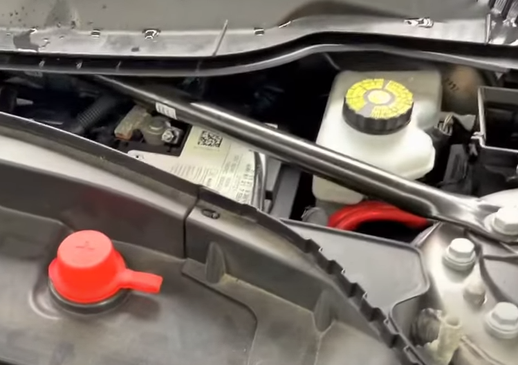
Disconnect battery
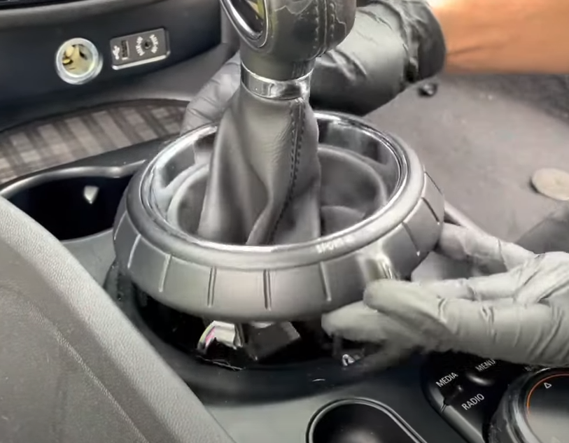
Detach gear shifter ring
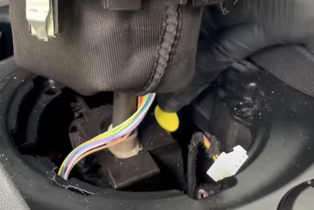
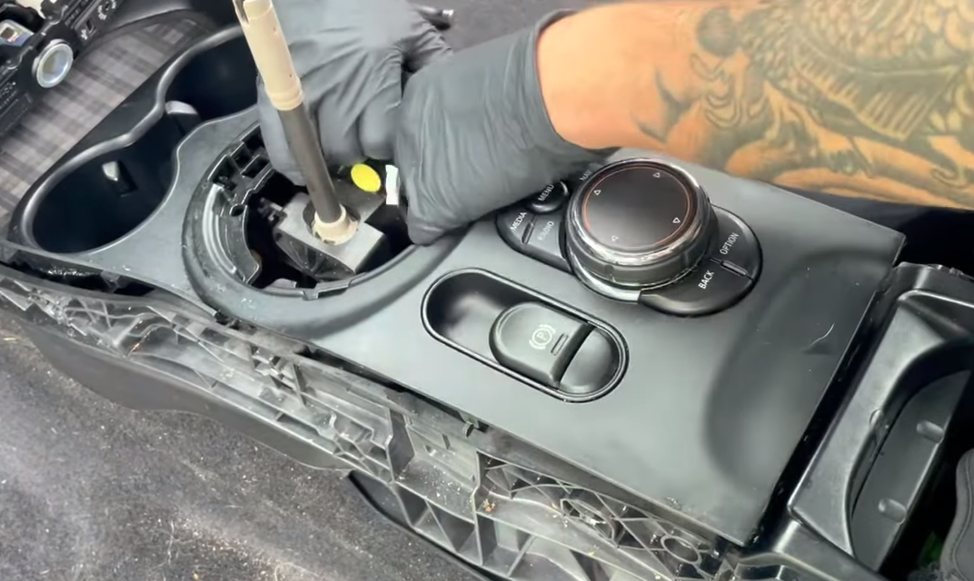
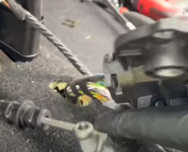
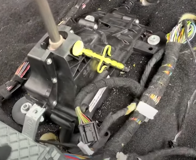
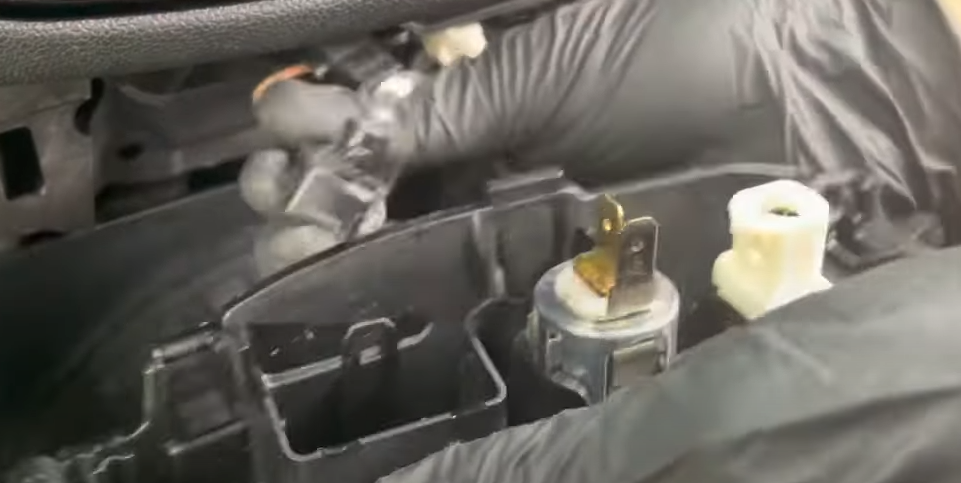
Press yellow tab and shift into neutral. Detach wiring harness
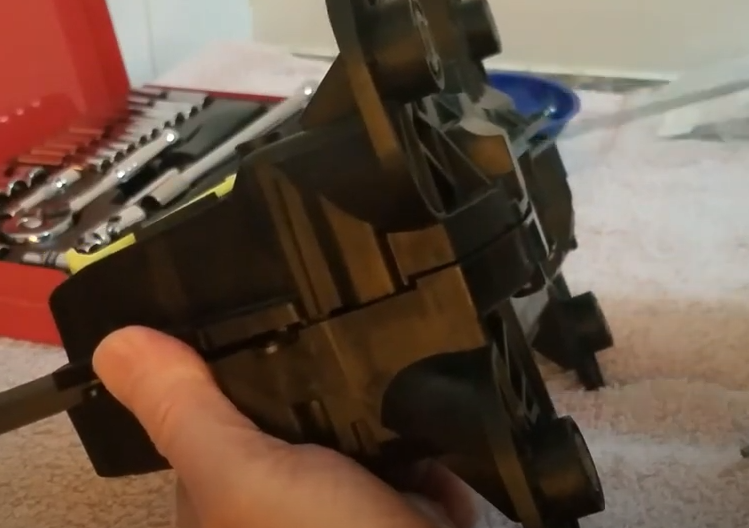
Pull up on shifter (hard) to remove it
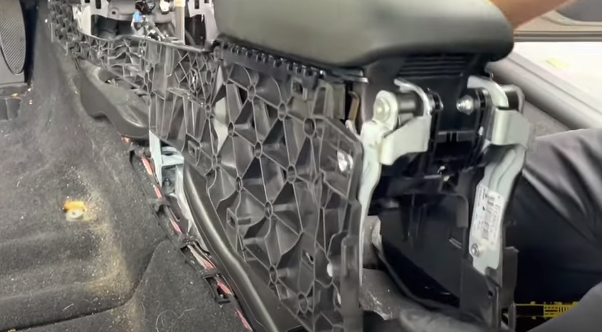
Remove kick panels (T20)
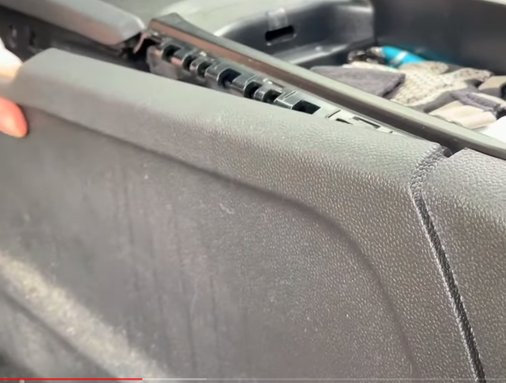
Remove side panels (they just pop apart with clips)
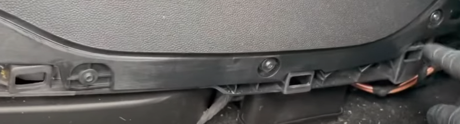
Remove screws under side panels
Remove rear plastic of center console, just pops off
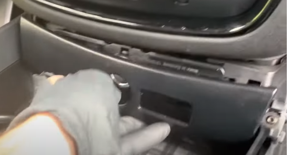
Disconnect cigarette lighter in rear
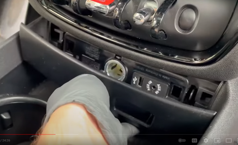
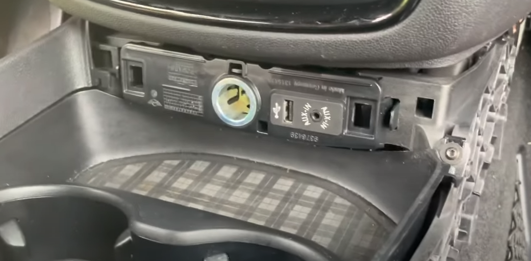
Pull off face for front cigarette lighter area
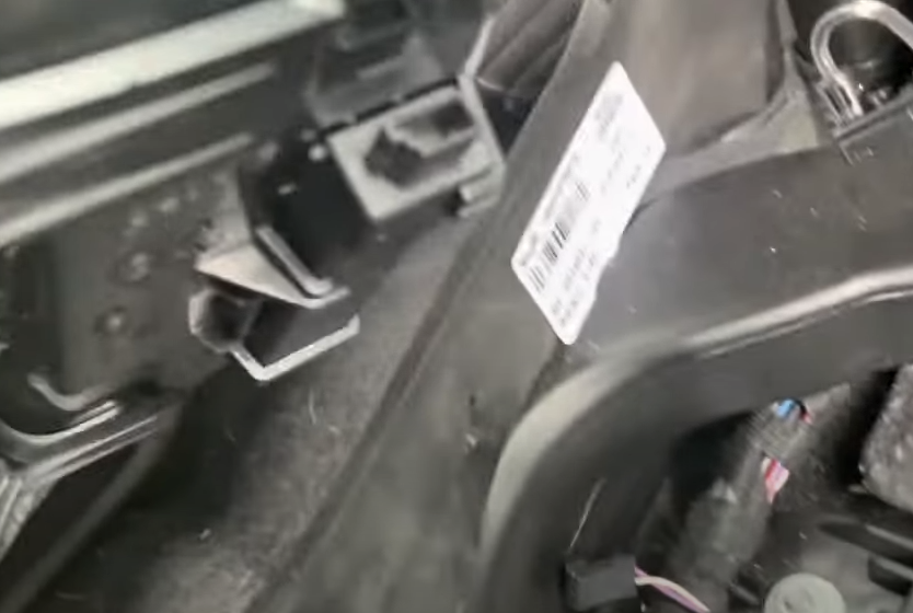
Remove lighter assembly (push in 2 tabs)
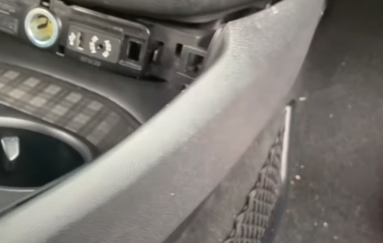
Pop off remaining side panels
Pull up on center console panel. Be careful of all the attached wiring
Detach 2 connectors
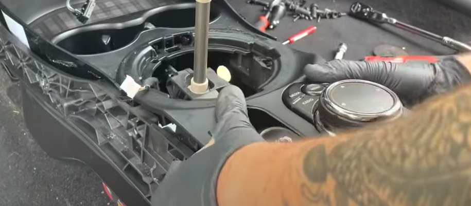
Remove 2 cupholder screws
Cupholder lifts out, there is a wiring harness so be careful
Unclip wiring harness from cupholder (there is only one)
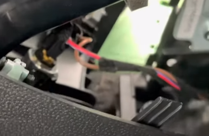
Unplug cigarette lighter and wiring harnesses
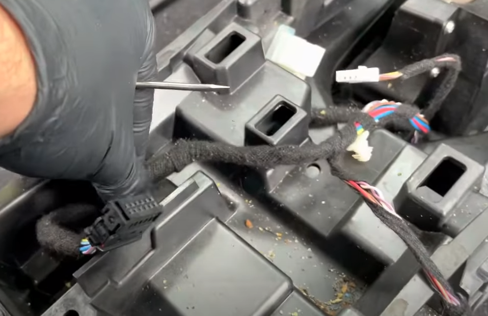
Detach all the remaining wiring harnesses from the center console
Pry retaining clip off the console
Remove wiring from rear module
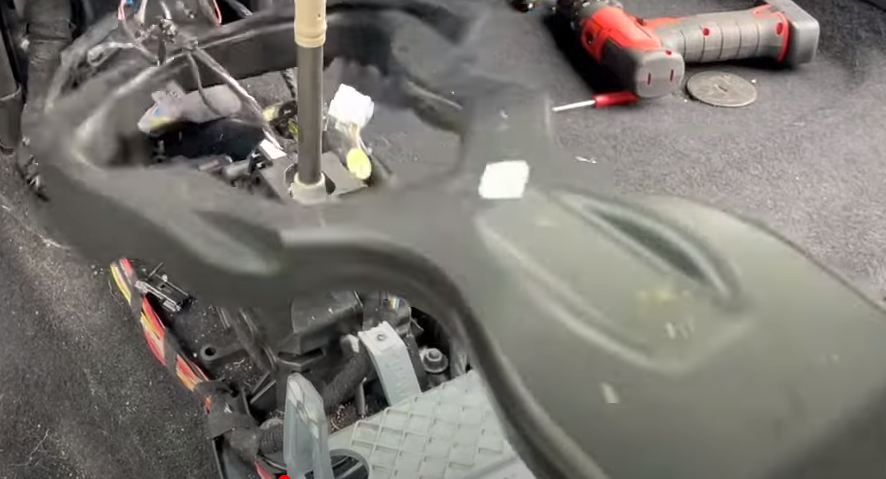
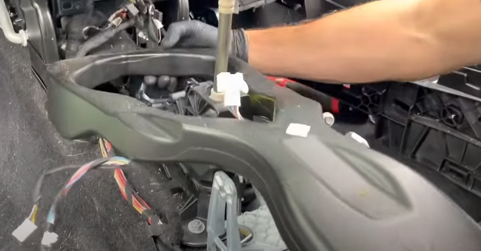
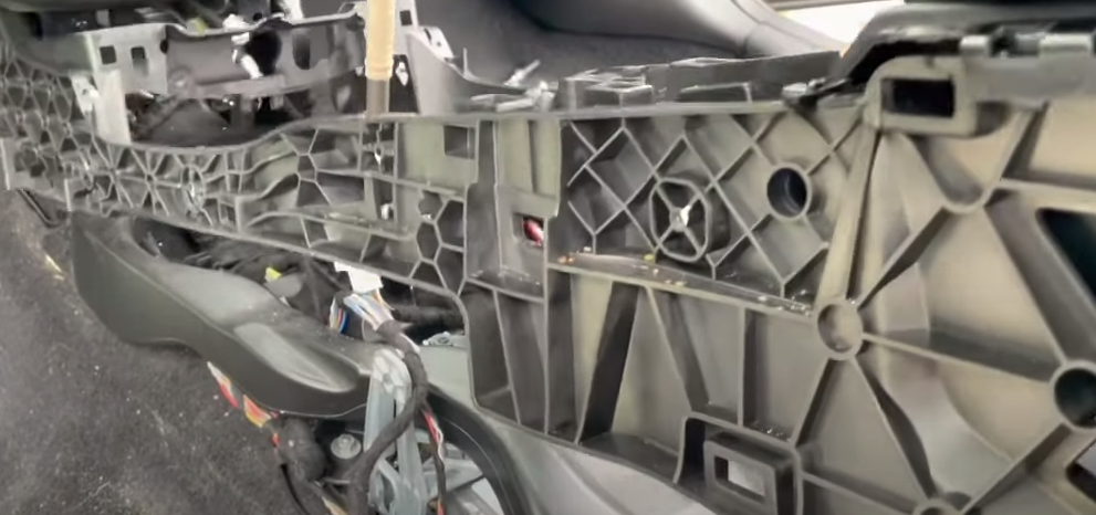
Lift out center console
Remove screw from remaining plastic
Lift out plastic
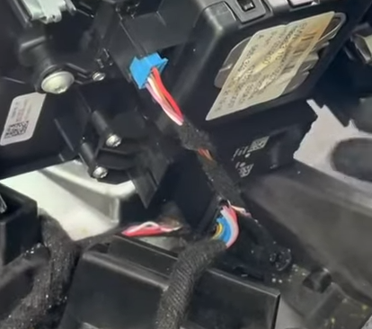
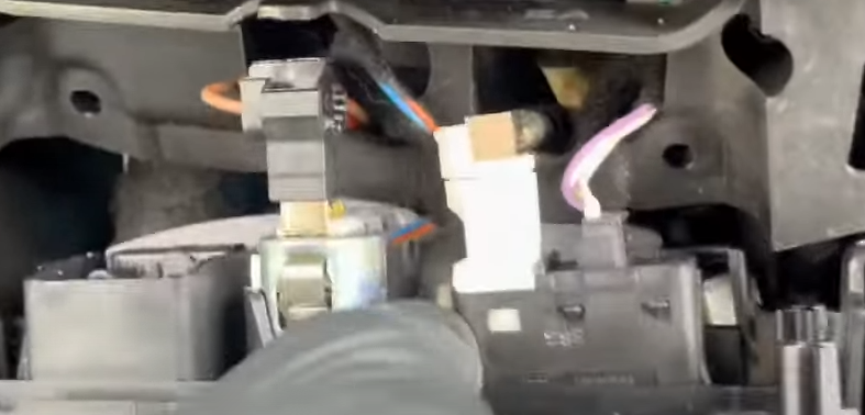
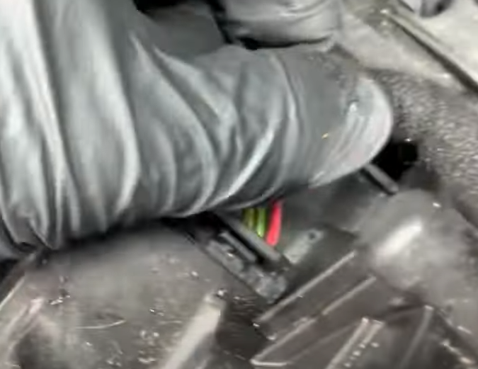
Disconnect remaining wiring retaining clips
Remove last wiring harness from shifter
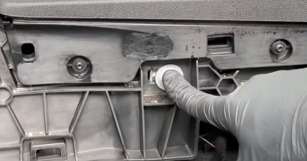
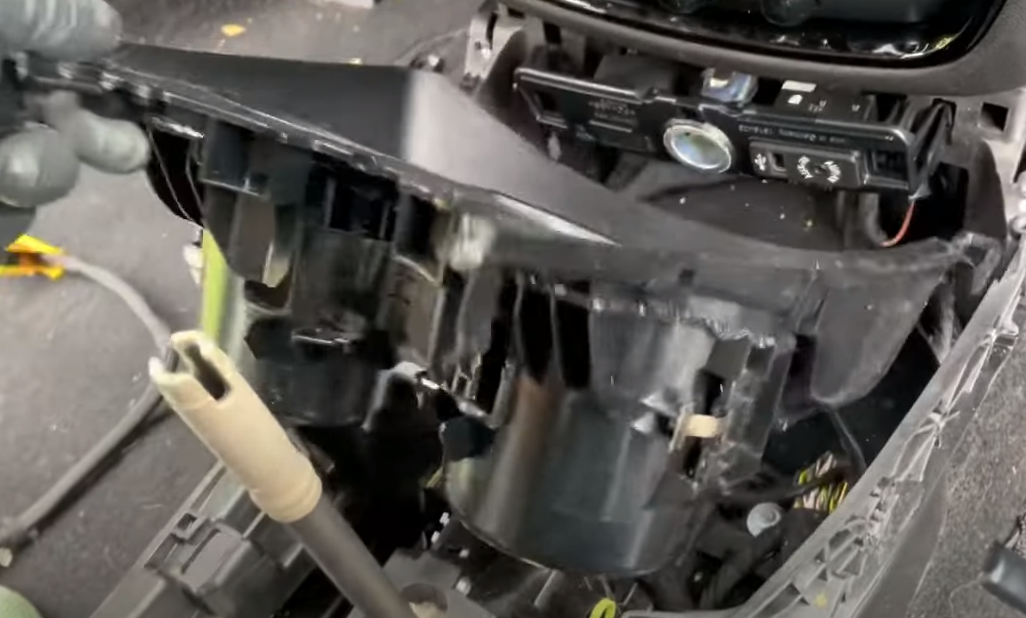
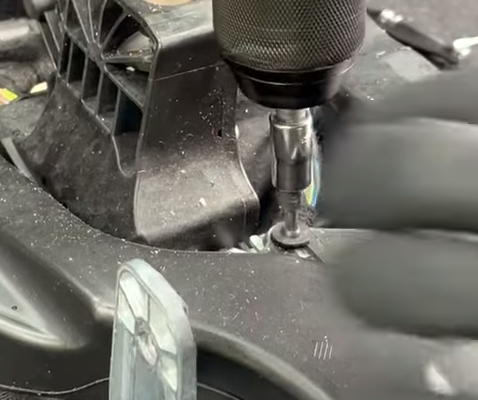
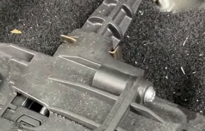
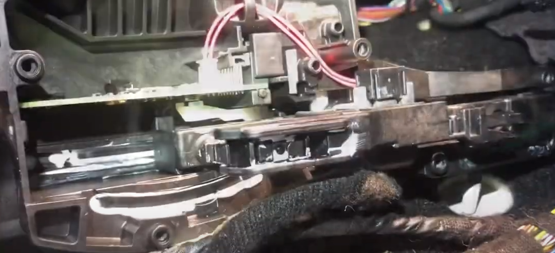
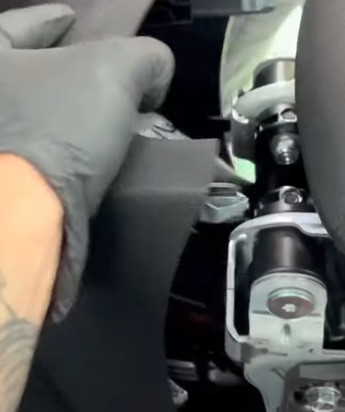
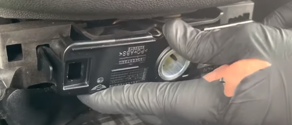
Pry off cable retaining clip from shifter assembly
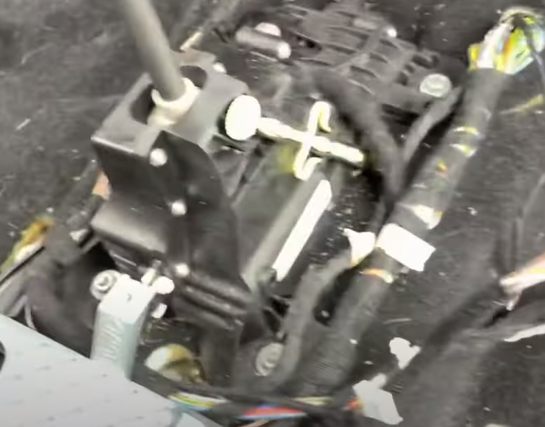
Remove the 4 silver nuts and lift up the shifter assembly
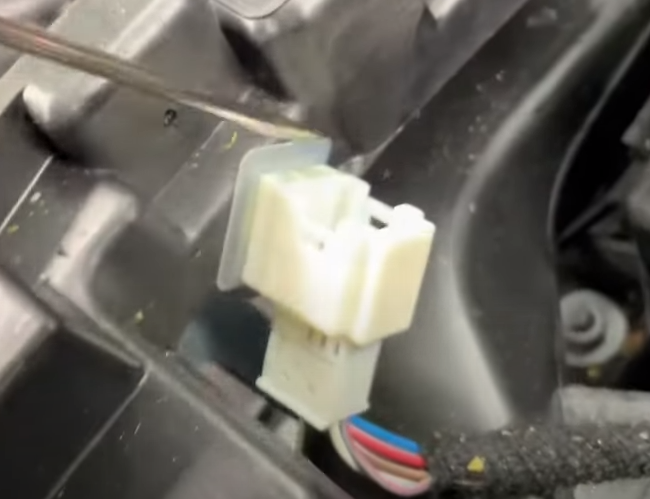
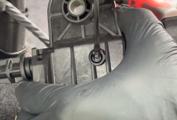
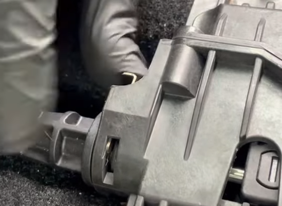
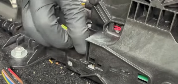
Align second retaining clip to center and push to remove
Detach assembly from cable and R&R assembly next
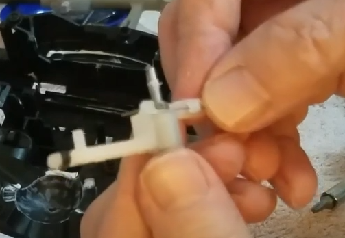
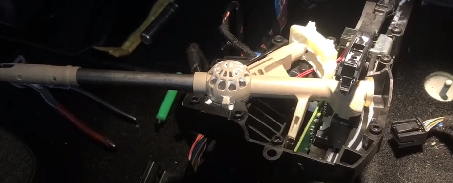
Gear Selector R&R / Spring Replacement
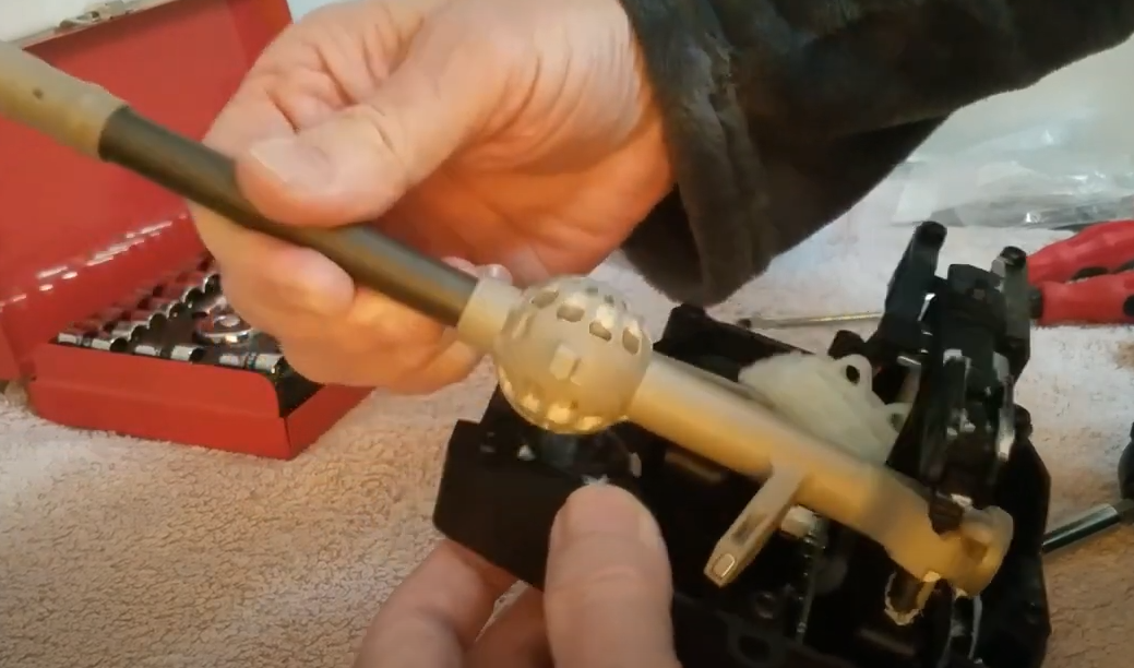
Unscrew housing
Separate housing carefully
Remove shifter arm
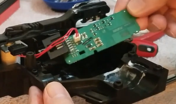
Remove circuit board
Remove plastic cantilever assembly
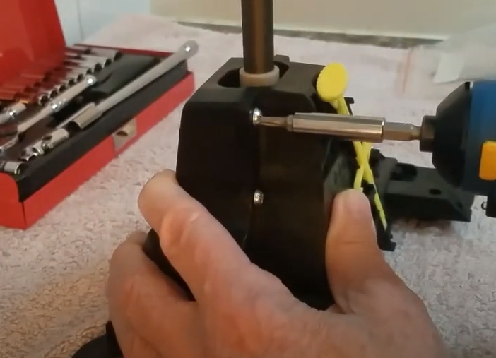
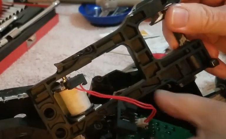
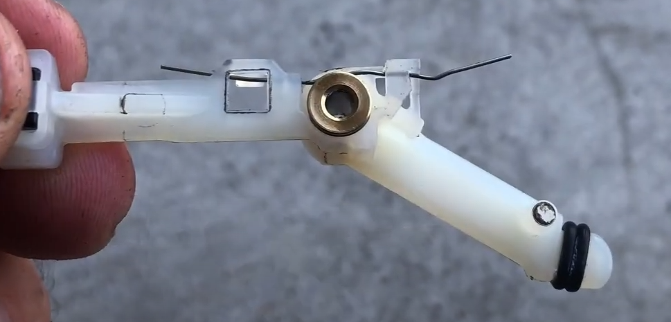
Use screwdriver to push out spring arm from bottom of housing
Push out pin from arm and remove spring
Install new spring. Spring arms should be straight/horizontal
Reinstall spring arm
Reinstall arm and circuit board
Reinstall shifter arm
Screw housing back together
Gear Shifter Reinstallation
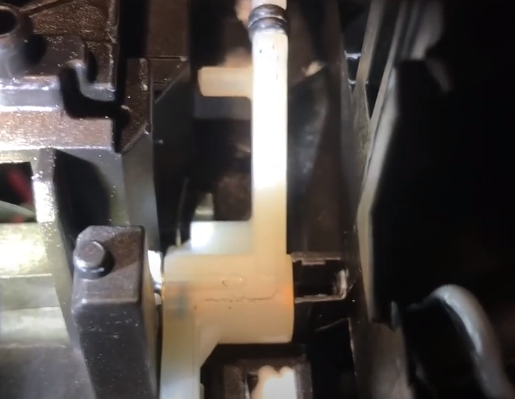
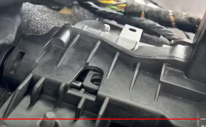
Slide in shifter cable and place shifter assembly onto the 4 bolt holes
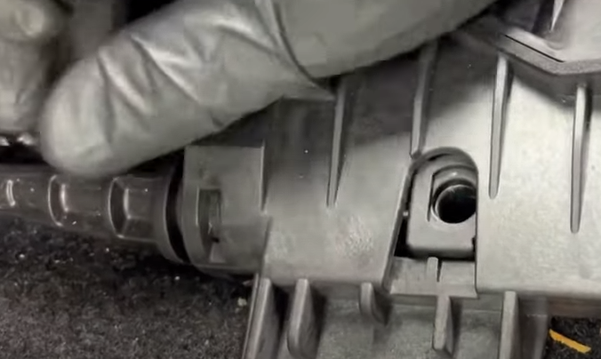
Reinstall shifter cable, align hole, and reinsert plastic clip
Reinstall shifter cable retaining clip
Reinstall nuts and wiring retaining clips
Reinstall wiring harness to shifter
Reinstall plastic cover
Reinstall center console. Make sure wires are routed correctly (i.e. cigarette lighter). Reconnect all wiring harnesses and connectors
Reinstall rear panel, reconnect wiring
Reinstall cupholder, reconnecting the wire to it
Snap center console top into place and reattach bolts/screws
Reinstall cigarette lighter and associated wiring
Reinstall 2 screws behind cigarette lighter panel
Snap cigarette lighter panel into place
Reinstall other screws for console top
Reinstall side panels
Reinstall trim
Reconnect battery
References:
For those who prefer videos, this one shows what you need to do to dismantle the center console. You don’t have to remove the seats, so you can save that step.
These videos show once we get the shifter out what needs to be done to open it up and replace the spring that went bad
I have a Line6 DT50 112 tube amp I love. But over Christmas, the power transformer failed. Line6 no longer makes parts, but it turns out Mercury Magnetic makes an aftermarket replacement. It’s pricey at $300, but given another used tub amp would be at least double that I figured it was worth trying to fix. Digging into the issue, I used this site as a guide to the replacement:
Fortunately all the wire colors seemed to line up. Unfortunately it seems the green/yellow strip wires for the center tap and filament are actually different voltages, and ultimately I released the “magic smoke”. Guitar Works in Evanston took about 4 months but eventually was able to find the issue and source the bad capacitors and fix it. So now I have a working amp. Mostly.
One of the cool features of the Line6 amps are that they can model different amp sounds. There’s a switch called “topology” which allows you to cycle through 4 different amp simulators. According to this site, topology I is a clean Fender, topology II is Marshall, III is a Vox, and IV is a Mesa Boogie.
Unfortunately whatever I did seems to have messed up the output from topology I and III, which are quite a bit quieter now than II and IV. I’m still debugging this via the schematics I found, but will likely need Guitar Works to take another look to find whatever other capacitor or analog component is bad and causing a lack of volume.
For those who have problems with this amp in the future, I ran across this set of schematics online. I’m not an electronics repair expert, but if you are or you have a trusted local guitar repair shop this doc might be really helpful in troubleshooting your problems. (And if someone out there is really good with schematics and can help me figure out why topology I and III are now too quiet, please write me or post a reply!)
After a few months of running my DIY lithium battery I thought I’d provide an update on it. We used the battery on our 5+ week trip out west, recharging it only via solar. In a few parks we had little to no sunlight during the day (Olympic National Park and North Cascades National Park were particularly deep within the tree canopy). Even still we never used more than 1/3 of the battery capacity during the trip. That was a huge improvement from prior trips where a few days in the shade and cold could result in us draining the lead acid battery down and then needing to break out jumper cables to recharge.
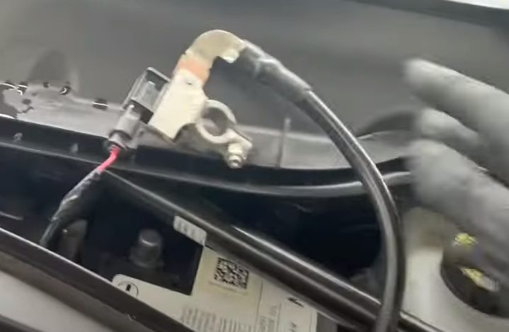
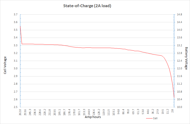
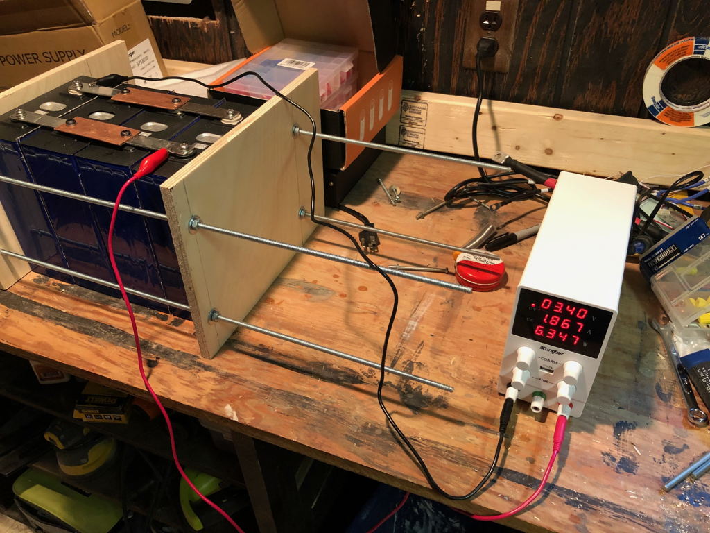
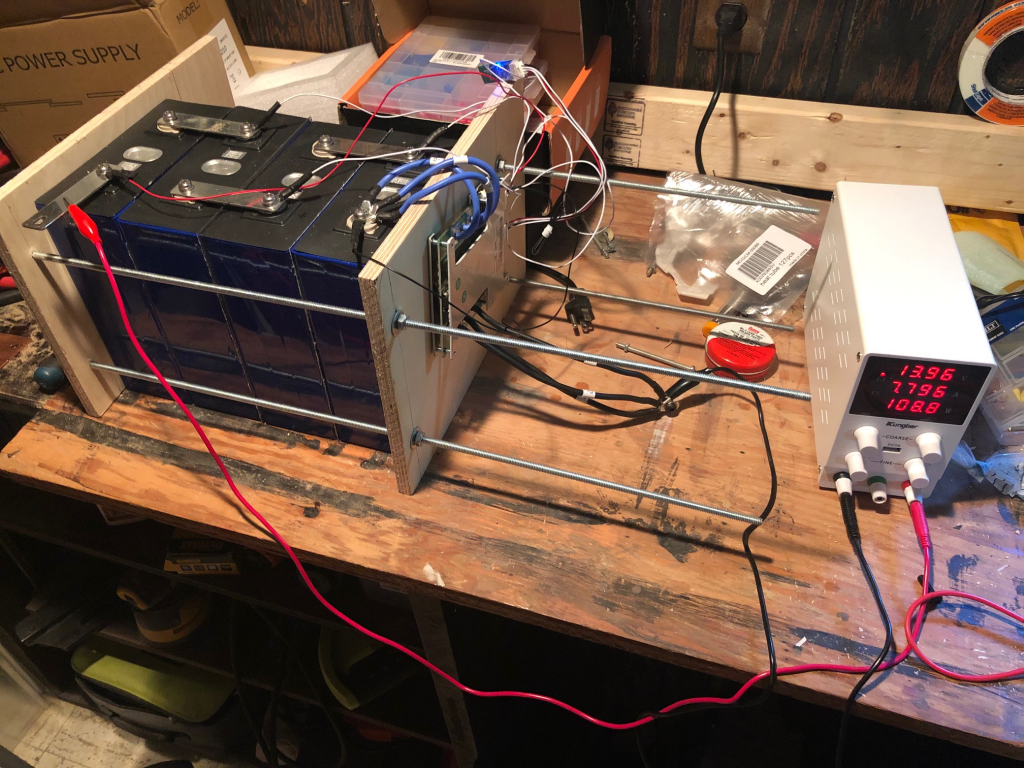
As cold weather is upon us I winterized the camper a couple weeks ago. This seemed like a good opportunity to do a true capacity test, so I pulled the battery off the camper and brought it home. I hooked it up my DC bench power supply and topped it off to 14.6V, then began a very slow capacity test by applying a steady 2A load.
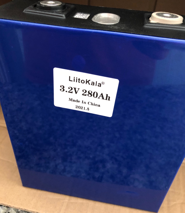
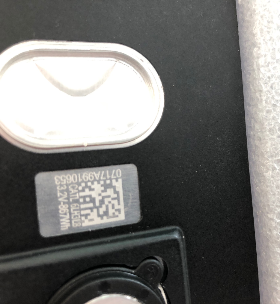
It took almost a week but the test is now complete. The cells I purchased were listed on the Liitokala store on AliExpress as 280Ah. While they had very generic “Liitokala 280Ah” stickers on them when they arrived, they also had official CATL QR codes which said they were 271Ah cells (867 Wh). Upon completing the test, I measured a total of 262Ah of capacity. That’s plenty for my purpose, though it leads me to believe the cells were either used or extremely poor quality as the official capacity is typically determined by running at a relatively high discharge rate (20%, 50%, or even 100%) whereas at 2A I was running at a very low rate (<1%). If my goal was to use these in a high discharge environment like an electric car I suspect they would have about 240Ah of capacity. In our trailer though they work well enough, especially given the cost
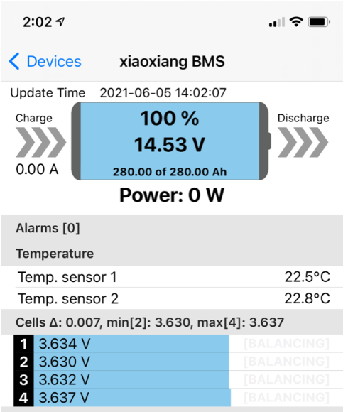
In part 2 I talked about my basic 12V setup and how I was top-balancing my new battery cells. I didn’t get into why to top-balance, but there’s an excellent explanation in the DIY Solar Forum – basically each cell is independent and we’re trying to equalize them and maximize the capacity of the pack. I more or less followed Will’s instructions which are also in the forum. However because my cells started out very close to the same voltage (within 0.001V), and my power supply is limited to 10 Amps, I just wired up my BMS and set it to 14.4V/8.5A and let it go. Even still it took ~24 hours to charge, implying the batteries arrived with about 30% charge.
After a few hours of charging… Eventually the cells start to diverge as they get near the top. Once this happened I re-wired in parallel, set the charger to 3.6V and 8.5A and let it go for the night. (Despite only only needing a few amps, at the top of the charge curve the power supply goes from constant current of 8.5A to constant voltage of 3.6V with a very low Amp rating (1.5A or less).
The last 10A took seemingly forever.
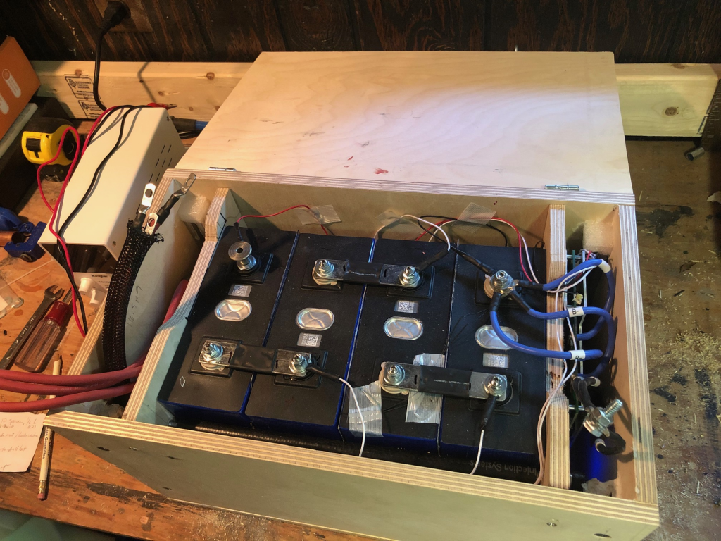
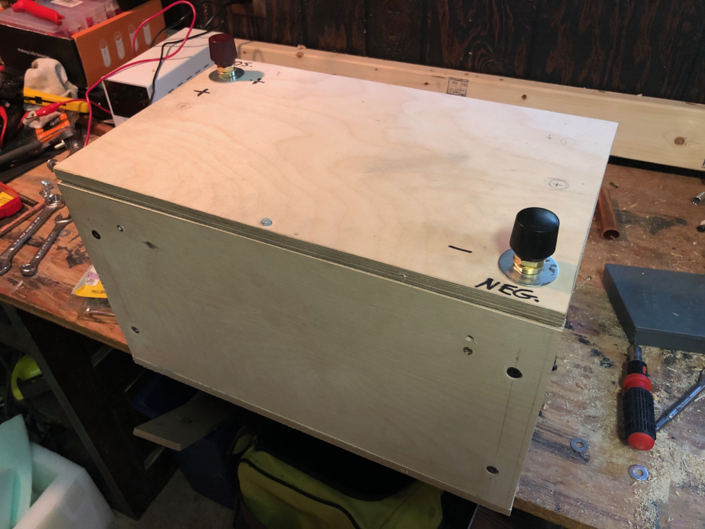
While the cells were charging, I started building the battery box to store (and protect) the cells, as their aluminum enclosures are relatively thin and there are quite a few wires and other electronics required. My goal was to build the main box in such a way that I could “drop” the compression frame with the cells and wiring inside. (Side note: Because LiFePO4 doesn’t tolerate cold, and also I’m not building a IP67 waterproof box, the final battery pack will need to fit inside the trailer in the cabinet underneath the fridge).
The batteries are sit inside a compression frame with the BMS mounted on the right side and a 150A fuse on the left. The frame drops into the box cleanly and applies light pressure to the cells via threaded rod and lock nuts on the ends. An ideal compression frame applies roughly 12psi evenly at all battery states, but the complexity of spring-loading the end plates was too much. Since my battery will stay at 70-90% SOC most of the time I just compressed for that.
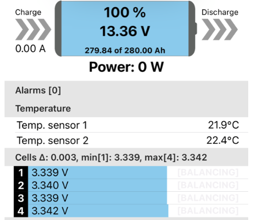
Box finished and battery fully charged!
It’s not fancy but since it will be hidden in a cabinet under our fridge, who cares? Final charge state.
Last step once complete was installation in the camper. I spent quite a bit more time on Sunday than anticipated re-routing the wiring for the solar charge controller and the main battery circuit. However it’s up and running now, with I believe only some minor tuning of the solar charge controller required to limit the battery charging to ~90% in order to extend the battery life.
First trip will be this weekend and we’ll see how it goes!
In my earlier post, I talked about what LiFePO4 batteries were and why I went with them. In this article I’ll cover how I built mine, which should allow most savvy DIYers to more or less repeat the process, building on what I learned. Most of what I learned about LiFePO4 batteries was from the DIY Solar Forum – if you’re truly interested in building your own battery I suggest reading the discussion forum there as well.
One note before I get started – this information is a general overview of what I did, how, and why. However, every battery is different (even LiFePO4, where different manufacturers may use different chemistries to construct their batteries) and every tool is unique. Furthermore, what worked for me might not work for you, and it’s entirely possible I omitted some critical details either accidentally or intentionally (for clarity). If you have no understanding of batteries or electronics and try to follow this step by step and end up blowing up your battery or burning down your house, that is not my fault. Build (and enjoy) at your own risk – part of the fun is learning as you go along.
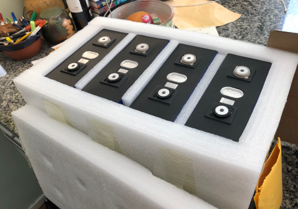
The largest cost for this project are the battery cells. Right now, decent quality 280Ah cells cost about $100 each from Alibaba or AliExpress, but you’ll need 4, and shipping from China is slow and expensive. Buying cells from China is also a bit risky – some suppliers will buy and re-brand cells, some will sell used cells, and some cells are lower quality (Grade “B” or “C”) or are “unmatched” (very different internal resistance or capacity). Shipping times vary greatly, and not all sellers will do a good job packing your cells so they may arrive damaged. AliExpress (and Alibaba, I think) offer delivery and other buyer guarantees, but in most cases you’ll need to ship the cells back to the seller at your cost to get a refund. Using a credit card with a good buyer protection policy is really important.
4 well-packed batteries arrived
All said I did a little research, but I also got a little lucky with my purchase from the LiitoKala store on AliExpress.
LiitoKala says 280Ah but the QR code says these are 867Wh @ 3.2V which is only 271Ah. I’m not yet sure if CATL de-rates their batteries a bit or if LiitoKala is stretching the truth.
The next major cost is your battery management system (BMS). While it’s technically possible to build a battery without a BMS, it’s generally a terrible idea and you should not do it. A quality BMS will provide a number of critical protections which will prevent you from destroying your very expensive battery cells quickly, including:
Low voltage cutoff (<2.5V) to prevent you from draining your battery below 1%.
High voltage cutoff (>3.65V) to prevent you from overcharging your cells
Temperature cutoff to prevent you from destroying your battery by trying to charge it below 0C or discharge it below ~20C, or conversely from trying to charge or discharge above 55C)
Automatic cell balancing, to ensure that all 4 cells keep the same voltage. This will slowly “steal” power from hotter (higher voltage) cells and trickle it to lower voltage cells, which maximizes your cell capacity and performance.
Since my BMS is rated for 120A, I built my battery to handle a continuous load of 120A. While I don’t have a 120V inverter right now, this allows me to add one up to 1500W to my camper at a later date without changing the battery. To handle 120A continuous load, I used three 8 gauge wires or heavy duty busbars for all connections. Note that 10AWG wires can carry up to 40A so three of them should handle 120A, but I believe in engineering a margin of safety into my design so stepping to 8AWG, which can handle 55A, ensures my battery wires will not overheat.
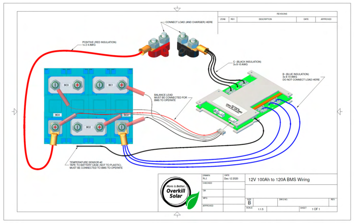
Overkill Solar 4S 120A BMS. (Overkill buys Xiaoxiang BMS, tests, configures, and re-brands them. I purchased the Xiaoxiang BMS from an eBay seller in the US for $105. You can get them cheaper off AliExpress, but I recommend paying a few extra dollars and buying one from Overkill Solar which has been tested and has a warranty).
150A fuse ($9) as your last line of defense in the event of a short
Heat shrink (various sizes) to help protect and strengthen your crimps (about $5)
Good quality 8AWG wire. I had some available but if you don’t then just buy a spool. Make sure you get real copper, not copper-clad aluminum (CCA) which has a much higher resistance
8 AWG lugs and 10 AWG lugs for battery terminal crimping. The battery terminals are M6 (6mm) and so 1/4″ battery lugs (6.3mm) will work. I needed six 10AWG lugs just for the BMS as mine came with 10AWG pre-soldered. If you bought the Overkill BMS with M6 terminals you’ll need double the number of lugs, and in that case I recommend using all 8AWG wiring. I use 8AWG for all other internal wiring, which means I needed 12 for the positive wiring as well – three 1/4″ for the positive M6 battery terminal, six 5/16″ for the fuse, and three 3/8″ for the exterior battery stud. Expect to spend about $20 on an assortment of sizes
If you go with the Overkill Solar BMS you’ll need 5 ring terminals to wire the leads. I used the red 18-22AWG ones with 1/4″ rings and I soldered the ends to make them thicker since I think the wires are even smaller ~26AWG.
Fiberglass strapping tape,($7) which is not strictly required but helpful to secure various things together (like attaching all 4 batteries)
I ordered a battery box ($15) from noco.com but then learned that you really should put your batteries in a compression frame, so ultimately I built mine out of some 1/4″ and 1/2″ birch plywood. I may still use the lid…
Some M6 “grub screws” (aka set screws) for $10, which you can permanently fix in the battery with some Loctite ($5). Throw the screws your battery comes with away – you can’t torque them properly anyway.
M6 washers, lock washers, and lock nuts. Home Depot or Ace Hardware have bags of these available. Don’t rely on a nut alone – always use a lock nut and/or lock washer.
If you’re building a compression frame, you’ll need some 1/2 plywood and four pieces of 1/4″-20 threaded rod about 18″ long, with 8x washers and lock nuts.
Tools
The following were things required that I didn’t own. If you have this stuff already, then great. If you don’t have screwdrivers, wrenches, a heat gun, and other miscellaneous tools then you’ll probably need to order those too.
You’ll need a Variable/Adjustable DC bench power supply in order to top-balance your cells. I bought the 30V/10A version and I’m really glad I did as even this one can take a couple days to fully charge your battery. Technically your BMS will probably be able to top-balance for you but at 30mV or less it could take weeks or months to complete if your cells do not arrive matched, and if they’re really far off it’s possible it might never complete.. If you want to be able to easily balance your battery and to be able to fully charge, then fully discharge, then properly re-charge your cells to confirm their capacity, just spend the $60.
A constant current load tester. I used one that runs $15 but you could do this with a 12V lightbulb or a bunch of resistors if you can measure the amperage accurately with a shunt.
A reliable multimeter.
I recommend a torque wrench designed to measure in/lbs, since if you overtighten your battery terminals you’ll strip them and end up very unhappy. They’re under $20 and often referred to as a “bicycle torque wrench” so you may find other uses for them in the future.
A decent wire crimper able to do anything 8 to 22AWG (or better)
Decent wire strippers. A heat gun (or aim-n-flame) will help with heat shrink too.
Step 1: Battery Cell Balancing
If you’re patient, the preferred method for doing the initial battery cell balancing is to connect the batteries in parallel (all + on one side, all – on the other), set the bench power supply up, adjust it to 3.6V and max Amps (or really 80% of max, just to preserve the power supply), and let it go until the Amps drops to 0. In fact that’s what I went to do at first. However my cells arrived with 60% charge (which is pretty typical) reading about 3.25V, which means I needed to put 112A in each battery to fully charge them. Even at 10A, that’s 44 hours… and the thing about batteries is that as you get the voltage closer to the current will drop to keep the voltage constant.
Cells wired in parallel in a (temporary) compression frame. If you don’t compress the cells slightly, they may swell. Power supply set to 3.4V and 8A, but once connected to cells which are 3.3V it switches from a constant 8A current to constant voltage, and the current drops off precipitously.
Rather than let the batteries sit on the charger for days, I decided to wire them in series, set up the BMS, and then apply a ~12V charge to the battery pack. This has the advantage of “only” needing to apply 112A to the pack, so it should take 1/4 the time. My expectation was that the cells were already matched (and probably balanced) within 0.01V so the BMS would take care of any balancing for me.
I set the power supply to 14V (which is 3.5V per cell) and 8A and let it run. Since I’m running through the BMS I suppose could just set it to 14.4V (3.6V per cell) or 14.6V (3.65V per cell) and count on the BMS to manage the cell voltage correctly, but since this is my first top-balance I wanted to give the BMS enough time to be able to balance the cells if they get too far out of whack as the voltage ramps up. I’ll repeat the process at 14.4V (3.6V per cell) once I’m sure the cells are balanced at 14V (3.5V per cell), or I’ll temporarily disconnect the busbars and individually top off a single cell if required.
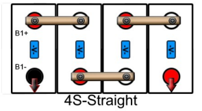
Basic 12V (4S or “4 battery Series”) wiring
Overkill Solar’s wiring diagram, also available on their websiteCells re-wired in series. and charging much faster now. Eventually once it’s charged I’ll cut down the threaded roads and build a (smaller) permanent battery box.
Our camper (travel trailer) has a typical 12V lead acid battery to run most of the devices. Solar does a decent job of keeping the battery topped up, but sometimes we end up in a campsite with a lot of shade and have been finding it increasingly hard to keep the battery sufficiently charged for 4-5 nights. This is particularly pronounced when we get up in higher elevations and will often run the heater at night to keep the temperature tolerable.
We’ve tried AGM batteries in the past but they’re roughly 2x the cost of a regular “wet” cell and don’t really provide much benefit. Honestly just replacing the $99 “deep cycle” battery every couple years has been more cost effective, though it rarely provides any major energy storage benefit. (Except the one time I killed a battery in Big Bend by running too many fans and draining it down to 10.5V overnight…)
I’ve been debating a lithium-based option like the Renogy or Battleborn drop-in LiFePO4 batteries for a while, but at $900 the price is steep for only a bit more capacity. Recently though a friend of mine turned me on to the DIY Solar Forum, where a bunch of people were building their own high capacity lithium batteries for a fraction of the cost. I did the math and decided to make the plunge, which ultimately led me down a rabbit hole in an effort learn everything I could as quickly as possible so I could build and test one before our next long summer trip.
This post has a number of acronyms or terms, which may be used interchangeably at times, even when the meaning isn’t 100% identical. Terms like:
SLA = Lead Acid battery (even for wet cell batteries which aren’t sealed). This is probably what’s in your car.
AGM = Absorbent Glass Mat battery (it’s like an SLA but actually sealed)
LiFePO4 is one of many lithium battery chemistries
Lithium Ion = LI = Li-ION or LION, which is a specific battery chemistry, probably in your cell phone
Lithium in this post refers to LiFePO4, even though it’s a generic term for all Lithium-based batteries
V = Volts
Ah = Amp hours. In a 12V battery, 10Ah means you can power a 12V device that draws 10A of current for 1 hour, or 1A of current for 10 hours. I will ignore battery efficient at low/high outputs
If you’re a purist, get over it.
Why Go Lithium?
Cheap lead acid batteries are available at Sam’s Club or Walmart for about $100. My last two Duracell 105Ah batteries came from Sam’s Club. They work, but unless you’re regularly on shore power or run a generator in my experience it’s really hard to get enough capacity from them. This is due to a few reasons.
First, the cheap “deep cycle marine” batteries in my experience are really inferior to high quality deep cycle batteries. I’ve read this is due to thinner plates, the use of recycled materials, etc. I can say from experience though that after two seasons, even with good maintenance practices, these tend to only have 70-80% capacity remaining. High quality AGM deep cycle batteries seem to hold up better over time (except when you completely drain them… d’oh!), but are roughly double the cost at $200-250. Lithium chemistries, on the other hand, are known for lasting thousands of cycles – the typical LiFePO4 battery will still have 80% of its capacity after 2000-3000 cycles, or roughly 7-10 years.
Second, you can use much more of your lithium battery capacity safely. Lead acid batteries should really not be discharged below 50% (though I will go as low as 30% sometimes), whereas lithium can be fully charged and discharged (though the manufacturers recommend keeping and using them in the 10%-90% range. Thus a 100Ah lead acid battery only has maybe 50-70Ah usable, whereas a 100Ah lithium battery is designed for 80% utilization but can be cycled up to 100% if desired.
Third, lithium chemistry batteries weight a LOT less than lead acid. Don’t believe me? Go check your periodic table. That $99 100Ah Duracell is 59lbs, while a 280Ah LiFePO4 battery pack (without the case) is only 50lbs.
So in short I expect given roughly the same space (Group 31 battery size) and weight (60 lbs) to normally have about 4x the usable capacity (230Ah, assuming 10-90% state of charge) vs the old lead acid battery (roughly 60Ah usable). [Note: If I fully cycle the LiFePO4 battery that’s 280Ah, and if I compare that to deep cycling the SLA battery that’s 70 or maybe 80Ah, so I feel the ~4x ratio holds].
Why Not Go Lithium?
There are really only a couple reasons not to do this. The first and most obvious is cost. While the actual cost to build a lithium battery with 4x capacity is on par with purchasing 4 high quality AGM batteries, in practice the latter doesn’t really make sense for me to do because of the weight and space required. (Also because I really don’t *need* more than ~150Ah of lead acid capacity).
The other reason is battery management. LiFePO4 batteries in particular don’t like being charged below freezing or discharged significantly below. In fact, charging your LiFePO4 battery when the cell temperature is below freezing is known to destroy them quickly. To compensate, the battery will need to be relocated inside the trailer and will need a battery management system. More on this in part 2…